AQ-F213E Feeder protection device
AQ-F213a_web_v3
AQ-F213a_web_v3

Description

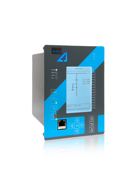
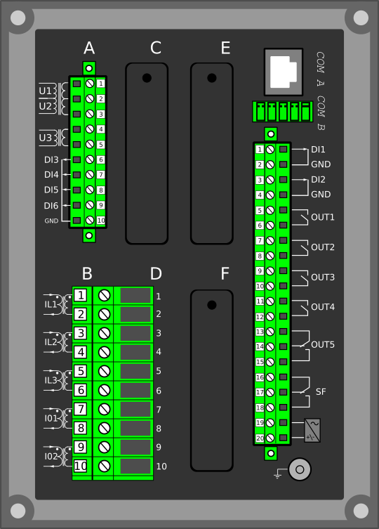
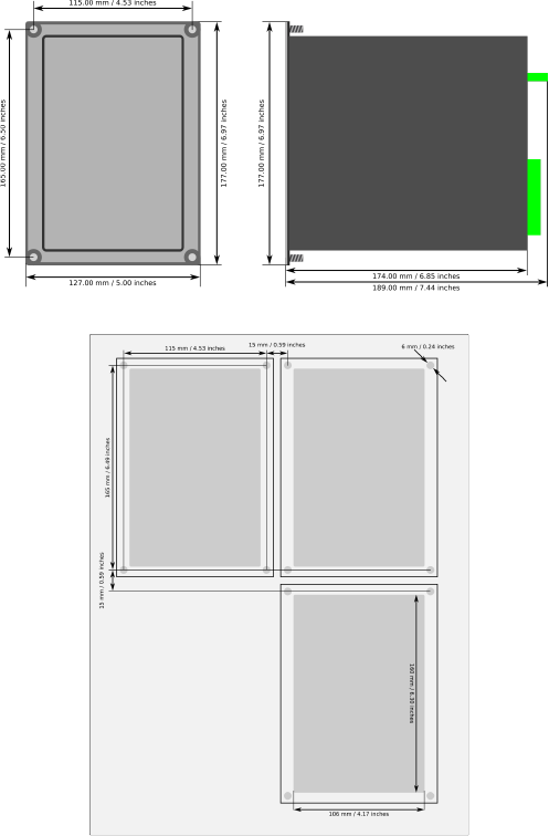
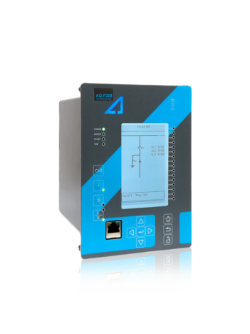
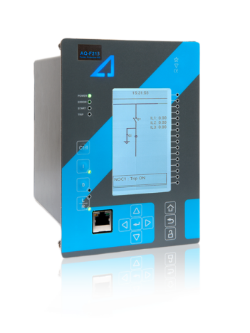
The AQ-F213E feeder protection device provides optimal performance for medium-voltage (main) or high-voltage (back-up) protection, control and monitoring applications. AQ-F213E integrates protection, control, monitoring, measuring, communication and extensive diagnostics information in one compact package. The device has a fully modular hardware construction with three (3) empty I/O slots. This gives the device a high level of flexibility. You can simply plug in additional I/O or communication modules according to application needs.

The development of the AQ-F213E feeder protection device uses the latest available technologies, which provides protection engineers with more options and a completely new dimension to protection. The device has many features which guarantee its maximum usability. These include the highly customizable graphic interface, the ability to store PDF files and other supportive documents, and extensive user log information. Additionally, the powerful configuration and setting software tools are easy to configure and free of charge.

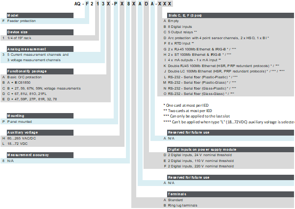
We offer five (5) variants of the AQ-F213 feeder protection device, A-E. AQ-F213E includes full functionality for feeder protection. In addition to all the basic current- and voltage-based protection functions, the E variant also includes additional functionalities, such as directional protections, the rate-of-change-of-frequency protection and various power protections.

Highlights:

  • Directional protections for overcurrent and earth faults.
  • Over-/underfrequency protection and rate-of-change-of-frequency protection.
  • Over-, under, and reverse power protections.
  • IEC 61850 communication protocol, edition 1.

See all AQ-F213 variants

AQ-F213a_web_v3

Technical data

  • Non-directional overcurrent (I>; 50/51) - 4 stages (INST, DT or IDMT)
  • Non-directional earth fault (I0>; 50N/51N) - 4 stages (INST, DT or IDMT)
  • Directional overcurrent (Idir>; 67) - 4 stages (INST, DT or IDMT)
  • Directional earth fault (I0dir>; 67N/32N) - 4 stages (INST, DT or IDMT)
  • Negative sequence overcurrent/ Phase current reversal/ Current unbalance (I2>; 46/46R/46L) - 4 stages (INST, DT or IDMT)
  • Harmonic overcurrent (Ih>; 50H/51H/68H) - 4 stages (INST, DT or IDMT)
  • Circuit breaker failure protection (CBFP; 50BF/52BF)
  • High-impedance or low-impedance restricted earth fault/ Cable end differential (I0d>; 87N)
  • Overvoltage (U>; 59) - 4 stages (INST, DT or IDMT)
  • Undervoltage (U<; 27) - 4 stages (INST, DT or IDMT)
  • Neutral overvoltage (U0>; 59N) - 4 stages (INST, DT or IDMT)
  • Sequence voltage (U1/U2>/<; 47/27P/59PN) - 4 stages (INST, DT or IDMT)
  • Overfrequency and underfrequency (f>/<; 81O/81U) - 8 stages (INST or DT)
  • Rate-of-change of frequency (df/dt>/<; 81R) - 8 stages (INST, DT or IDMT)
  • Overpower (P>; 32O)
  • Underpower (P<; 32U)
  • Reverse power (Pr; 32R)
  • Line thermal overload (TF>; 49F)
  • Resistance temperature detectors (RTD)
  • Voltage memory
  • Arc protection (IArc>/I0Arc>; 50Arc/50NArc) (optional)

  • Number of objects to control and monitor: 5
  • Number of indicators to monitor: 5
  • Number of setting groups: 8
  • Cold load pick-up
  • Switch-on-to-fault
  • Auto-recloser (0 → 1; 79)
  • Vector jump (Δφ; 78)

  • Phase, sequence and residual currents (IL1, IL2, IL3, I01, I02)
  • Phase, sequence and residual voltages (UL1, UL2, UL3, U12, U23, U31, U0)
  • Frequency (f)
  • Power (P, Q, S, pf) and Energy (E+, E-, Eq+, Eq-)
  • Current transformer supervision
  • Voltage transformer supervision (60)
  • Circuit breaker wear monitoring
  • Total harmonic distortion (current)
  • Total harmonic distortion (voltage)
  • Fault locator (21FL)
  • Measurement recorder
  • Measurement value recorder
  • Event recorder (max. 15 000 permanent event records)
  • Disturbance recorder (max. 100 records á 5 seconds at 3.2 kHz sampling)

  • Current inputs: 5
  • Voltage inputs: 3
  • Digital inputs (fixed): 6
  • Digital outputs (fixed): 5
  • Number of empty slots: 3
  • Digital inputs: +8/16/24 (optional)
  • Digital outputs: +5/10 (optional)
  • Milliampere I/O module (4 mA outputs + 1 mA input)
  • Arc protection module (4 sensors + 2 HSO + 1 BI)
  • Communication media (see "Communication" below)
  • External I/O modules (see "Accessories" below)

  • Communication inputs
  • RJ-45 100 Mbps Ethernet (front panel, fixed)
  • RJ-45 100 Mbps Ethernet and RS-485 (rear panel, fixed)
  • 2 x RJ-45 100 Mbps Ethernet with an IRIG-B input (optional)
  • 2 x ST 100 Mbps Ethernet with an IRIG-B input (optional)
  • 2 x LC 100 Mbps Ethernet (PRP/HSR) (optional)
  • RS-232 serial fiber (PP/PG/GP/GG) (optional)
  • Communication protocols
  • IEC 61850 (edition 1)
  • IEC 60870-5-101/104
  • IEC 60870-5-103
  • Modbus/RTU and Modbus/TCP
  • DNP3
  • SPA

  • AX007 External 6-channel 2-/3-wire RTD input module (pre-configured)
  • AX008 External 8-channel thermocouple and mA input module (pre-configured)
  • AX009 Raising frame (87 mm)
  • AX010 Raising frame (40 mm)
  • AX011 Combiflex frame
  • AX012 Wall mounting bracket

Additional material

Application Drawing

An application image for AQ-F213E feeder protection device, with one version drawn according to IEC standard symbols and the other according to IEEE/ANSI standard symbols.

Device Rear Image

Device rear image_AQ-213-AAA

Device and Cut-out Image

AQ-210 dimensions and cut-out

Order Code

Order code_F213x

Related products

AQ-F213_web_cropped

AQ-F213 Feeder protection devices

The AQ-F213 feeder protection devices provide optimal performance for medium-voltage (main) or high-voltage (back-up) protection, control, […]

Ask for an offer or more information

We provide a comprehensive range of services through our own skilled staff and a global network of partners.