AQ-G257 Generator protection device
AQ-G257_web
AQ-G257_web

Description

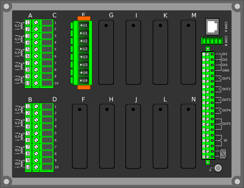
The AQ-G257 generator protection device is well-suited for large machines that require complete generator protection and differential protection. The device has an integrated automatic voltage regulator function. You can add up to nine (9) I/O or communication modules into the device for extensive monitoring and control applications. You can also connect up to sixteen (16) RTD signals for thermal alarming and tripping. AQ-G257 communicates using various protocols, including the IEC 61850 substation communication standard.

The AQ-G257 generator protection device has two software options: the “A” variant (AQ-G257A) includes all the standard generator protection functions, while the “B” variant (AQ-G257B) also includes the synchronizer function. For more details on the software options, please see the order code below.

Highlights:

  • Complete synchronous machine protection
  • Integrated differential protection
  • Power measurement accuracy of up to 0.2 %
AQ-G257_web

Technical data

  • Non-directional overcurrent (I>; 50/51) - 4 stages (INST, DT or IDMT)
  • Non-directional earth fault (I0>; 50N/51N) - 4 stages (INST, DT or IDMT)
  • Directional overcurrent (Idir>; 67) - 4 stages (INST, DT or IDMT)
  • Directional earth fault (I0dir>; 67N/32N) - 4 stages (INST, DT or IDMT)
  • Negative sequence overcurrent/ Phase current reversal/ Current unbalance (I2>; 46/46R/46L) - 4 stages (INST, DT or IDMT)
  • Harmonic overcurrent (Ih>; 50H/51H/68H) - 4 stages (INST, DT or IDMT)
  • Circuit breaker failure protection (CBFP; 50BF/52BF)
  • High-impedance or low-impedance restricted earth fault/ Cable end differential (I0d>; 87N)
  • Voltage-restrained overcurrent (Iv>; 51V)
  • Overvoltage (U>; 59) - 4 stages (INST, DT or IDMT)
  • Undervoltage (U<; 27) - 4 stages (INST, DT or IDMT)
  • Neutral overvoltage (U0>; 59N) - 4 stages (INST, DT or IDMT)
  • Sequence voltage (U1/U2>/<; 47/27P/59PN) - 4 stages (INST, DT or IDMT)
  • Overfrequency and underfrequency (f>/<; 81O/81U) - 8 stages (INST or DT)
  • Rate-of-change of frequency (df/dt>/<; 81R) - 8 stages (INST, DT or IDMT)
  • Power protection (P, Q, S>/<; 32) - 4 stages (DT)
  • Volts-per-hertz overexcitation (V/Hz>; 24)
  • Underexcitation (Q<; 40)
  • Underimpedance (Z<; 21U)
  • Underreactance (X<; 21/40)
  • Pole slip/Out-of-step protection (78)
  • Inadvertent energizing (I>U<I.A.E.; 50/27)
  • Resistance temperature detectors (RTD)
  • Machine thermal overload (TM>; 49M)
  • Generator/transformer differential (Idx>; 87T/87M/87G)
  • Power factor protection (PF<; 55)
  • 100 % stator earth fault (U03rd>; 64S)
  • Voltage memory
  • Programmable stage (PGx>/<; 99)
  • Arc protection (IArc>/I0Arc>; 50Arc/50NArc) (optional)

  • Number of objects to control and monitor: 10
  • Number of indicators to monitor: 10
  • Number of setting groups: 8
  • Vector jump (Δφ; 78)
  • Synchrocheck (ΔV/Δa/Δf; 25)
  • AQ-G257B – Synchronizer (ΔV/Δa/Δf; 25)

  • Phase, sequence and residual currents (IL1, IL2, IL3, I01, I02)
  • Phase, sequence and residual voltages (UL1, UL2, UL3, U12, U23, U31, U0)
  • Frequency (f)
  • Power (P, Q, S, pf) and Energy (E+, E-, Eq+, Eq-)
  • Power and energy class 0.5
  • Power and energy measurement accuracy of up to 0.2 % (optional)
  • Current transformer supervision - 2 instances
  • Voltage transformer supervision (60)
  • Circuit breaker wear monitoring
  • Total harmonic distortion (current)
  • Total harmonic distortion (voltage)
  • Measurement recorder
  • Measurement value recorder
  • Event recorder (max. 15 000 permanent event records)
  • Disturbance recorder (max. 100 records á 5 seconds at 3.2 kHz sampling)

  • Current inputs: 10
  • Voltage inputs: 4
  • Digital inputs (fixed): 3
  • Digital outputs (fixed): 5
  • Number of empty slots: 9
  • Digital inputs: +8/16/24/32/40/48/56/64/72 (optional)
  • Digital outputs: +5/10/15/20/25/30 (optional)
  • Milliampere I/O module (4 mA outputs + 1 mA input)
  • Arc protection module (4 sensors + 2 HSO + 1 BI)
  • Communication media (see "Communication" below)
  • External I/O modules (see "Accessories" below)

  • Communication inputs
  • RJ-45 100 Mbps Ethernet (front panel, fixed)
  • RJ-45 100 Mbps Ethernet and RS-485 (rear panel, fixed)
  • 2 x RJ-45 100 Mbps Ethernet with an IRIG-B input (optional)
  • 2 x ST 100 Mbps Ethernet with an IRIG-B input (optional)
  • 2 x LC 100 Mbps Ethernet (PRP/HSR) (optional)
  • RS-232 serial fiber (PP/PG/GP/GG) (optional)
  • Communication protocols
  • IEC 61850 (edition 1)
  • IEC 61850 (edition 2)
  • IEC 60870-5-101/104
  • IEC 60870-5-103
  • Modbus/RTU and Modbus/TCP
  • DNP3
  • SPA

  • AX007 External 6-channel 2-/3-wire RTD input module (pre-configured)
  • AX008 External 8-channel thermocouple and mA input module (pre-configured)
  • AX013 Raising frame (120 mm)
  • AX014 Raising frame (40 mm)
  • AX015 Wall mounting bracket

Additional material

Application Drawing

An application image for AQ-G257A generator protection device, with one version drawn according to IEC standard symbols and the other according to IEEE/ANSI standard symbols.

Device Rear Image

Device rear image_AQ-257-AAAAAAAAA

Device and Cut-out Image

AQ-250 dimensions and cut-out

Order Code

Order code_G257

Related products

Ask for an offer or more information

We provide a comprehensive range of services through our own skilled staff and a global network of partners.