AQ-M210 Motor protection device
AQ-M210_web_v3
AQ-M210_web_v3

Description

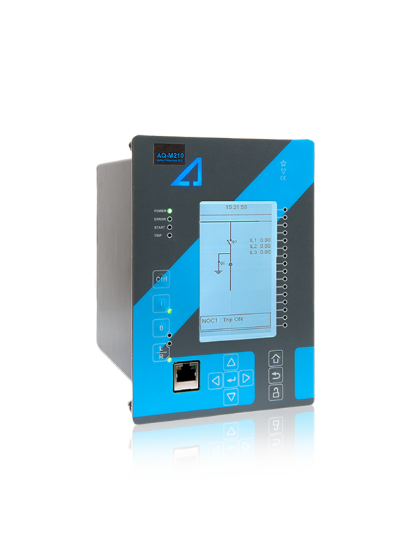
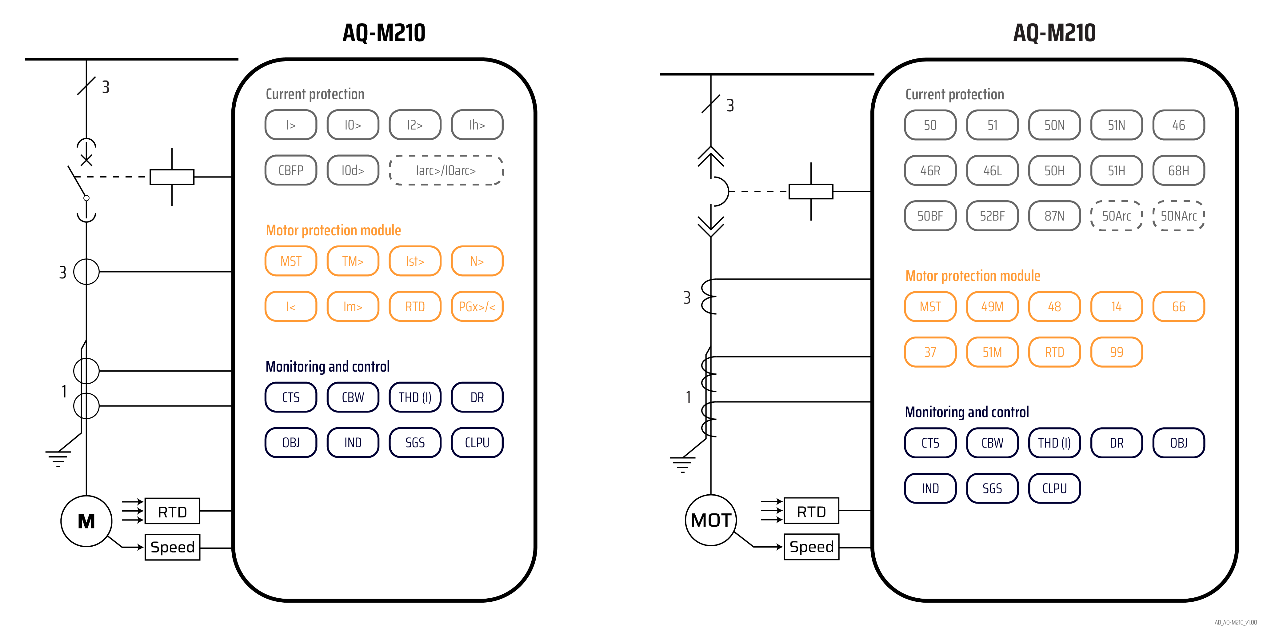
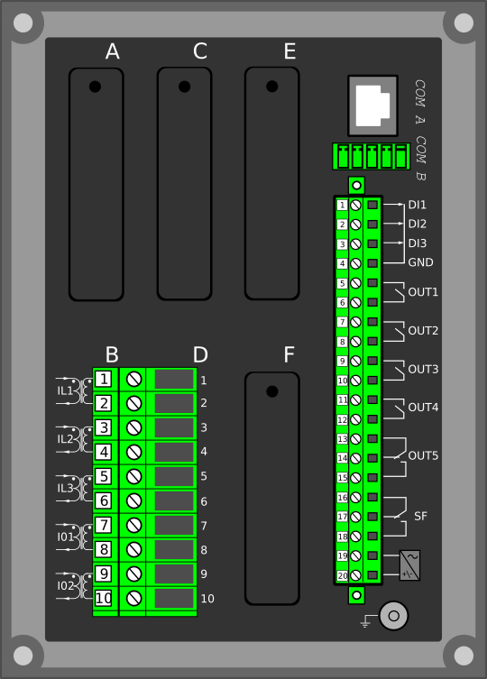
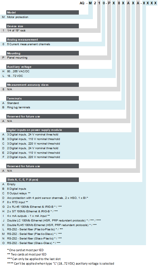
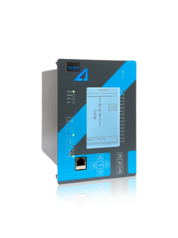
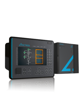
The AQ-M210 motor protection device offers a modular protection and control solution for small and medium-sized motors. You can add up to four (4) I/O or communication cards into the device for more comprehensive monitoring and control applications. You can also connect up to twelve (12) RTD signals for thermal alarming and tripping. AQ-M210 communicates using various protocols, including the IEC 61850 substation communication standard.
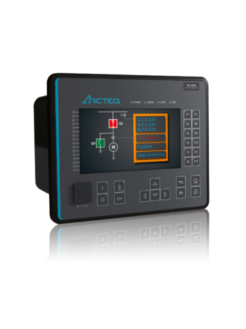
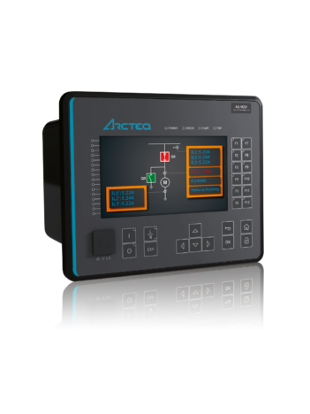
 Highlights:

  • Five (5) thermal models (time constant accurate).
  • Soft start protection begins from 6 Hz.
  • Wye-delta started motor supervision.
  • Two-speed motor protection.
AQ-M210_web_v3

Technical data

  • Non-directional overcurrent (I>; 50/51) - 4 stages (INST, DT or IDMT)
  • Non-directional earth fault (I0>; 50N/51N) - 4 stages (INST, DT or IDMT)
  • Negative sequence overcurrent/ Phase current reversal/ Current unbalance (I2>; 46/46R/46L) - 4 stages (INST, DT or IDMT)
  • Harmonic overcurrent (Ih>; 50H/51H/68H) - 4 stages (INST, DT or IDMT)
  • Circuit breaker failure protection (CBFP; 50BF/52BF)
  • High-impedance or low-impedance restricted earth fault/ Cable end differential (I0d>; 87N)
  • Resistance temperature detectors (RTD)
  • Machine thermal overload (TM>; 49M)
  • Motor status monitoring
  • Motor start/ Locked rotor monitoring (Ist>; 48/14)
  • Frequent start (N>; 66)
  • Non-directional undercurrent (I<; 37)
  • Mechanical jam (Im>; 51M)
  • Programmable stage (PGx>/<; 99)
  • Arc protection (IArc>/I0Arc>; 50Arc/50NArc) (optional)

  • Number of objects to control and monitor: 5
  • Number of indicators to monitor: 5
  • Number of setting groups: 8
  • Cold load pick-up

  • Phase, sequence and residual currents (IL1, IL2, IL3, I01, I02)
  • Current transformer supervision
  • Circuit breaker wear monitoring
  • Total harmonic distortion (current)
  • Running hour counter
  • Measurement recorder
  • Measurement value recorder
  • Event recorder (max. 15 000 permanent event records)
  • Disturbance recorder (max. 100 records á 5 seconds at 3.2 kHz sampling)

  • Current inputs: 5
  • Digital inputs (fixed): 3
  • Digital outputs (fixed): 5
  • Number of empty slots: 4
  • Digital inputs: +8/16/24/32 (optional)
  • Digital outputs: +5/10 (optional)
  • Milliampere I/O module (4 mA outputs + 1 mA input)
  • Arc protection module (4 sensors + 2 HSO + 1 BI)
  • Communication media (see "Communication" below)
  • External I/O modules (see "Accessories" below)

  • Communication inputs
  • RJ-45 100 Mbps Ethernet (front panel, fixed)
  • RJ-45 100 Mbps Ethernet and RS-485 (rear panel, fixed)
  • 2 x RJ-45 100 Mbps Ethernet with an IRIG-B input (optional)
  • 2 x ST 100 Mbps Ethernet with an IRIG-B input (optional)
  • 2 x LC 100 Mbps Ethernet (PRP/HSR) (optional)
  • RS-232 serial fiber (PP/PG/GP/GG) (optional)
  • Communication protocols
  • IEC 61850 (edition 1)
  • IEC 60870-5-101/104
  • IEC 60870-5-103
  • Modbus/RTU and Modbus/TCP
  • DNP3
  • SPA

  • AX007 External 6-channel 2-/3-wire RTD input module (pre-configured)
  • AX008 External 8-channel thermocouple and mA input module (pre-configured)
  • AX009 Raising frame (87 mm)
  • AX010 Raising frame (40 mm)
  • AX011 Combiflex frame
  • AX012 Wall mounting bracket

Additional material

Application Drawing

An application image for AQ-M210 motor protection device, with one version drawn according to IEC standard symbols and the other according to IEEE/ANSI standard symbols.

Device Rear Image

Device rear image_AQ-210_AAAA

Device and Cut-out Image

AQ-210 dimensions and cut-out

Order Code

Order code_M210

Related products

Ask for an offer or more information

We provide a comprehensive range of services through our own skilled staff and a global network of partners.