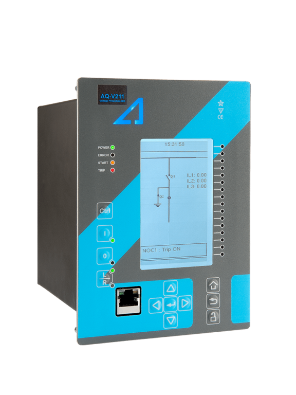
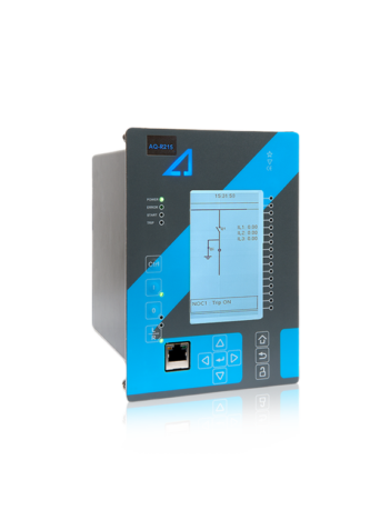
The AQ-V211 voltage protection device offers a modular voltage protection solution for substations. The relay includes both voltage and frequency protections as well as powerful logic programming, and you can add up to five (5) I/O or communication cards. All this makes AQ-V211 optimal for demanding load shedding and automatic transfer applications. AQ-V211 communicates using various protocols, including the IEC 61850 substation communication standard.
The AQ-V211 voltage protection device comes in two variants: the “A” variant (AQ-V211A) includes the standard functionalities for voltage protection, while the “B” variant (AQ-V211B) also includes the synchronizer function.
Highlights:
Eight (8) frequency stages and eight (8) setting groups for load shedding.
Synchrocheck for up to three (3) circuit breakers.
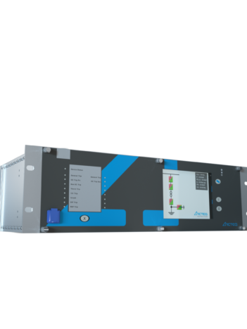
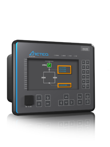
The AQ-C255A capacitor bank protection device has been specifically designed for the protection of capacitor banks. […]
Ask for an offer or more information
We provide a comprehensive range of services through our own skilled staff and a global network of partners.
Privacy Overview
This website uses cookies so that we can provide you with the best user experience possible. Cookie information is stored in your browser and performs functions such as recognising you when you return to our website and helping our team to understand which sections of the website you find most interesting and useful.
Strictly Necessary Cookies
Strictly Necessary Cookie should be enabled at all times so that we can save your preferences for cookie settings.
3rd Party Cookies
This website uses Google Analytics to collect anonymous information such as the number of visitors to the site, and the most popular pages.
Keeping this cookie enabled helps us to improve our website.
Please enable Strictly Necessary Cookies first so that we can save your preferences!